01 / Explore the plant and current products
A tank system often needs local indication, point-level control, continuous transmission and flow monitoring at the same time. Our interactive illustration connects each measurement task to its location. Select a number for application details and product links, or use the list below on mobile.
The illustration explains instrument functions and their relationship within a system. Selection, connections, wiring and control logic must suit your fluid, pressure, temperature and equipment. Our technical team can help define the requirements.
One plant illustration, eight instrument locations
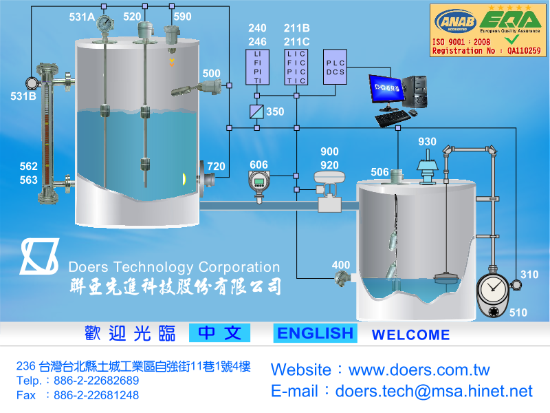
Side-mounted level and transmission
Use the flags for local inspection; specify a compatible transmitter for a control-room value.
High / low level contacts
Point-level signals using side- or top-mounted floats to suit the vessel connections.
Non-contact level
Top-mounted ultrasonic measurement: check dead zone, foam, vapor and obstructions.
Pipeline flow
For water service, compare paddlewheel sensing with compatible transmission and electromagnetic measurement.
Process control valves
Specify upstream/downstream pressure, flow, actuation and fail position together.
Sump and pump level
Cable floats provide point signals; allow travel and prevent entanglement.
Temperature and pressure
These variables govern the process and other instruments; check materials, ranges and insertion length.
Signal display and totalization
Match field signals to compatible displays, scaling and required totalization functions.
02 / Tank: indication, switching and transmission
Local inspection: 562 / 563 / 564 magnetic gauges provide a flag boundary. Compare 541 / 542 glass gauges when color or interface observation is needed. Both require compatible connections, fluid and service access.
Point switching: 500 side-mounted floats, 520 top-mounted floats or compatible 528 / 529 external switches serve contact-based tasks. Pump operation also needs control, electrical interlocks and suitable protection; the switch is not the complete system.
Continuous monitoring: a 531 transmitter or a 590 ultrasonic instrument in suitable service sends information to indication/control equipment. Confirm output, span, supply and mounting before defining display and alarms.
03 / Pipeline: value, visual flow and no-flow detection
For cooling water, compare a 630 electromagnetic meter or a 600 sensor with compatible indication/transmission when the control room needs a flow value. For a local reading, consider a variable-area meter. Conductivity, cleanliness and velocity guide the choice.
For visual flow presence, consider the 644 sight-flow indicator; for a low-flow contact, assess a switch separately. Oil totals may lead to a 624A/B positive-displacement assessment. These pipeline instruments are not interchangeable.
04 / Pressure, temperature and valves in context
Pressure and temperature determine instrument, seal and valve suitability as well as supporting inspection. Temperature sensors and thermowells require suitable materials, insertion lengths and flow conditions. Pressure gauges require the right range, wetted materials and pulsation assessment.
Select control valves such as 900 / 920 using fluid, flow, upstream/downstream pressure, actuation and fail-position requirements. The illustrated piping and signal lines explain roles, not valve sizing, wiring or protection design.
05 / Turn your application into a configuration
Start with a vessel or piping sketch showing where you need level indication, signals, point control and flow measurement. Add fluid, pressure/temperature, ranges, connections and supply to match each location to products and accessories.
You can also describe the problem: pump dry-running, poor level visibility or inconsistent filling totals. Identify whether the issue is measurement, reading, control or maintenance before selecting an instrument.
Explore related products and specifications
- 562 / 563 / 564 Series Magnetic Level Gauges →
- 500 Series Side-Mounted Float Level Switches →
- 520 Series Magnetic Float Level Switches →
- 531 Series Magnetic Level Transmitters with 4–20 mA Output →
- 590 Series Ultrasonic Level Transmitters →
- 506 Series Cable Float Level Switch Assemblies →
- 630 Series Electromagnetic Flow Meters →
- 600 Series Paddlewheel Flow Sensors →
- 606 Series Flow Transmitters with LCD Rate and Total Displays →
- 400 Series / 410 Series RTD and Thermocouple Temperature Sensors →
- 710 Series Pressure Transmitters →
Product technical documents
We help match the model and accessories to your fluid, pressure, temperature, installation and signal requirements. Share your application details with our technical team for a configuration review.
Discuss your application with Doers ↗