

Magnetic Level Gauges
The 562/563/564 magnetic level gauges provide a passive local flag display. For continuous remote monitoring, Doers pairs the gauge with a 531 series transmitter for a two-wire 4–20 mA DC output. HART communication is optional, and 528/529 switches can provide separate high/low alarms. Wetted materials, float and thermal protection are selected for the process.
- Model
- 562 / 563 / 564 Series
- Category
- Level
- Revision
- Updated 2026-09-24
Selection guidance and FAQs
Magnetic coupling and flag indication
Magnetic describes the coupling between the float magnet and the external indicator; flag describes the rotating visual indicator. In the 562 / 563 / 564 family, the indicator is isolated from the process liquid and follows the float position. Confirm the full configuration rather than selecting on terminology alone.
How do 562, 563 and 564 differ?
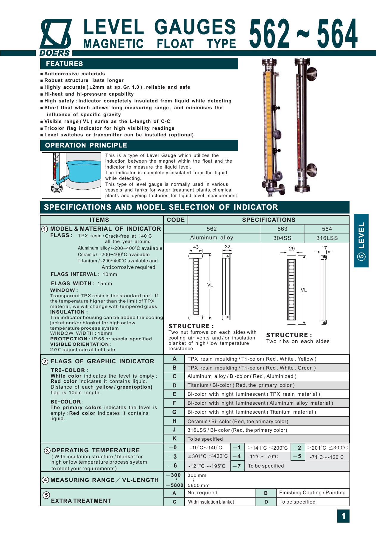
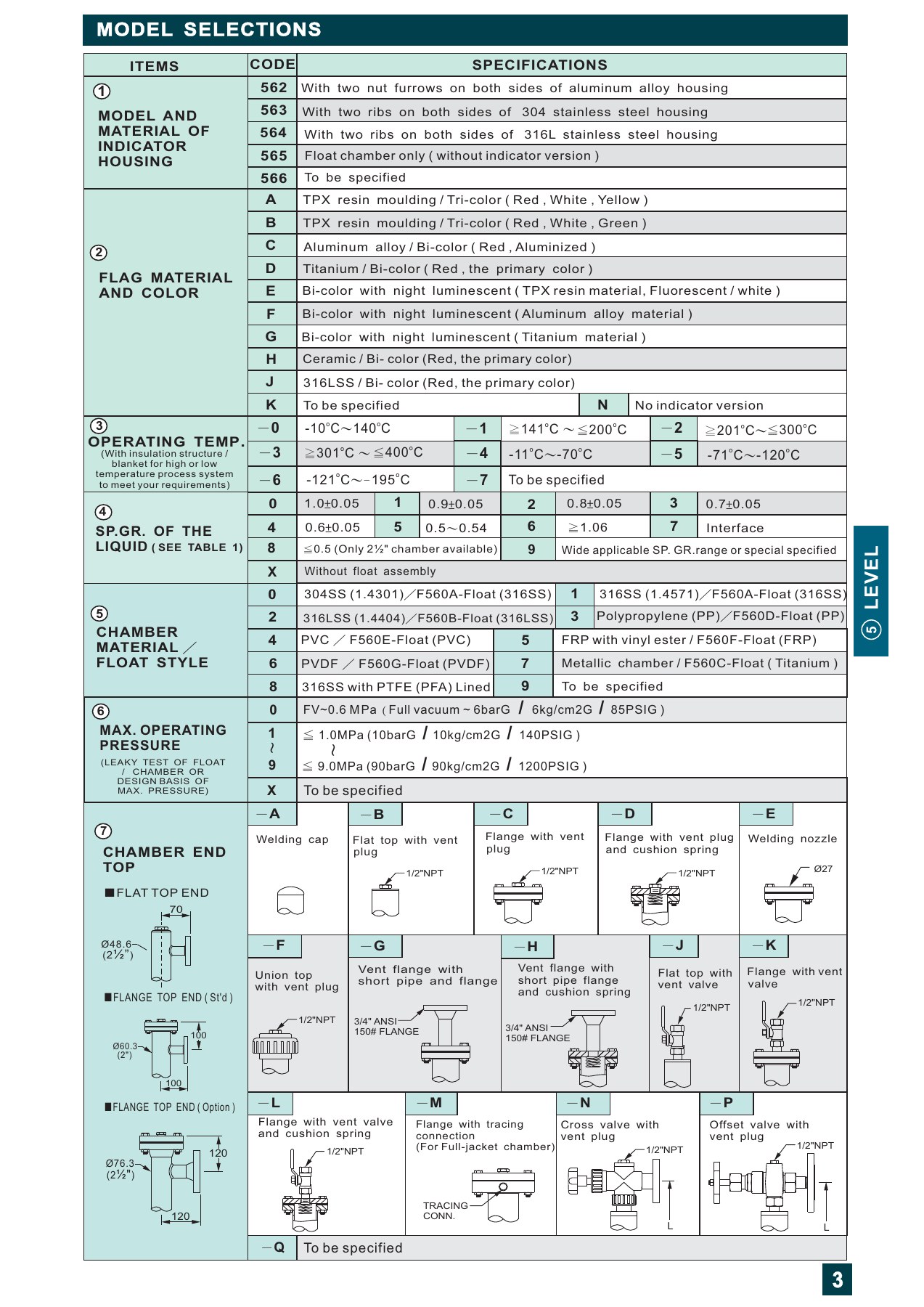
The 562, 563 and 564 use aluminum alloy, 304 stainless steel and 316L stainless steel indicator housings. Select the wetted chamber, float, gaskets and valves separately for the fluid, concentration and operating conditions.
Can a magnetic level gauge provide 4–20 mA?
Yes. Doers pairs the 562/563/564 with a 531 series transmitter for two-wire 4–20 mA DC, with optional HART. The 528/529 provide level-switch alarms. The 530 is a resistance-output detector, unlike the 531 transmitter with signal conversion. Confirm mounting, span, supply and thermal protection for the assembly.
Related products and specifications
- 531 two-wire 4–20 mA / HART transmitters →
- 528 / 529 level switch options →
- 530 magnetic level detector →
- Compare reflex and transparent gauges →
Our technical team can help confirm the options and operating limits for your application.
Discuss your application with Doers ↗Technical specifications
| Parameter | Specification | Unit |
|---|---|---|
| Indicator housing | 562: aluminum alloy; 563: 304 stainless steel; 564: 316L stainless steel | |
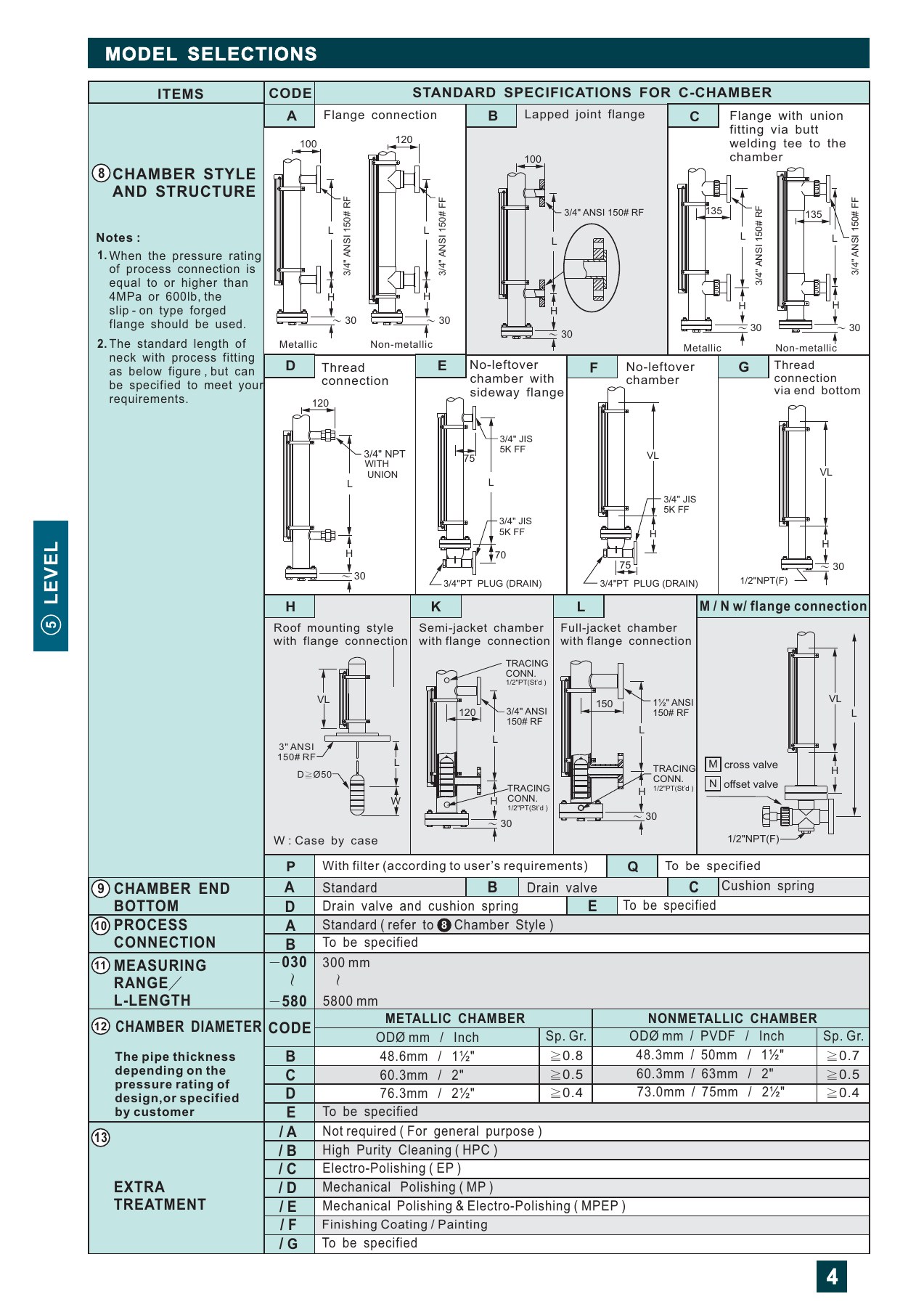
| Visible/measuring length options | 300–5,800, subject to configuration | mm |
| Indication accuracy condition | ±2 mm at a liquid specific gravity of 1.0 | |
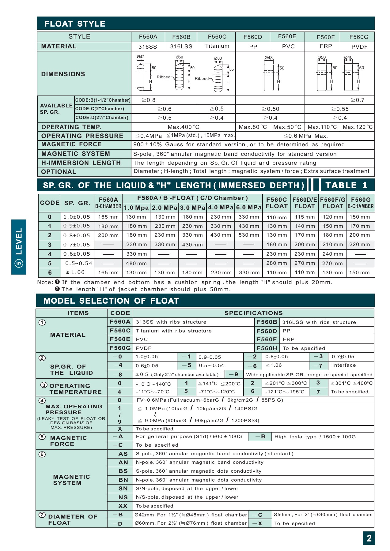
| Chamber material options | 304, 316 or 316L stainless steel; PP, PVC, PVDF or FRP; lined versions also available | |
| Metal chamber outside diameter options | 48.6, 60.3 or 76.3; wall thickness depends on design pressure | mm |
| Flag options | TPX tri-color or bi-color aluminum, titanium, ceramic or 316L options, selected for the configuration and temperature | |
| Continuous output and alarms | 531 series: two-wire 4–20 mA DC, optional HART; 528/529: optional separate level switches | |
| Interface measurement | Interface float selection based on both liquid densities and their difference; application review required |
Application and selection notes
- Indicator housing material and wetted chamber material are separate selections.
- Provide liquid specific gravity at operating temperature, plus operating and design temperature and pressure, to select the float and chamber. Do not combine limits from different configurations.
- Confirm nozzle center-to-center distance, flange stand-off from the tank, and access for venting, draining and float removal.
- Corrosive, crystallizing or viscous fluids require a review of wetted materials, insulation or heat tracing, and float movement.
- The 530 is a resistance-output detector. The 531 includes signal conversion and provides 4–20 mA when paired with the magnetic gauge; the 530 output specification does not describe the complete 531 transmitter.
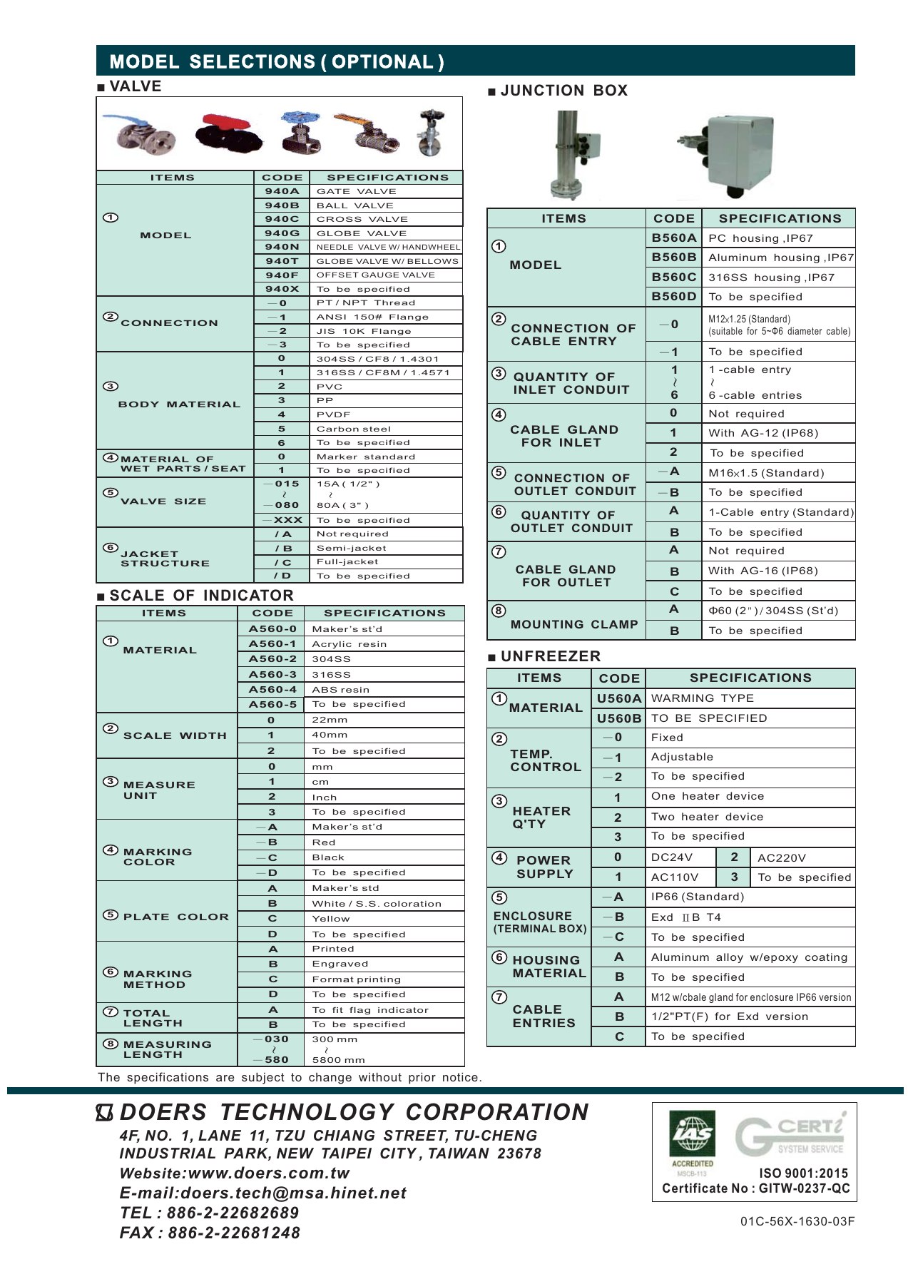
Verify specifications and options against the documents for your model. Select a technical sheet to enlarge it.
Documents
Related products


Explore the principles behind your selection
Need help selecting for your application?
Bring your fluid, temperature, pressure, installation and signal requirements to our technical team.
Level and flow measurement planning →