

Reflex & Transparent Level Gauges
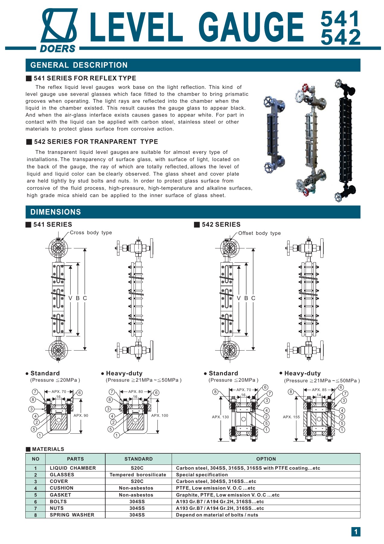
The 541 reflex gauge uses light and dark contrast to indicate liquid level. The 542 transparent gauge allows observation of the level and fluid appearance through opposing glass panels. Glass, chamber, gasket and valve options must suit the observation task and process conditions.
- Model
- 541 / 542 Series
- Category
- Level
- Revision
- Updated 2026-09-24
Selection guidance and FAQs
How does the 541 reflex gauge work?
The 541 uses optical reflection to create a visual contrast between the gas and liquid sections. Verify compatibility with the wetted materials and glass, as well as the temperature, pressure and visible-length requirements.
What can the 542 transparent gauge show?
Front and rear glass on the 542 allow light through the chamber to show level, liquid appearance and, under suitable conditions, liquid-liquid interfaces. Mica shields and non-frosting options are selected against lighting, fluid, temperature, pressure and assembly requirements.
Can reflex and transparent gauges be interchanged?
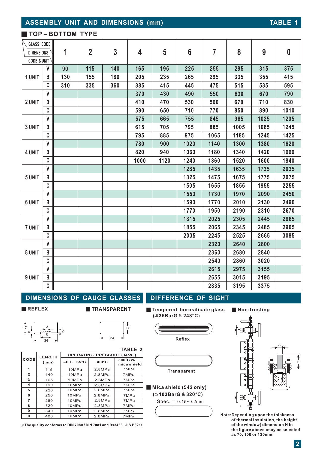
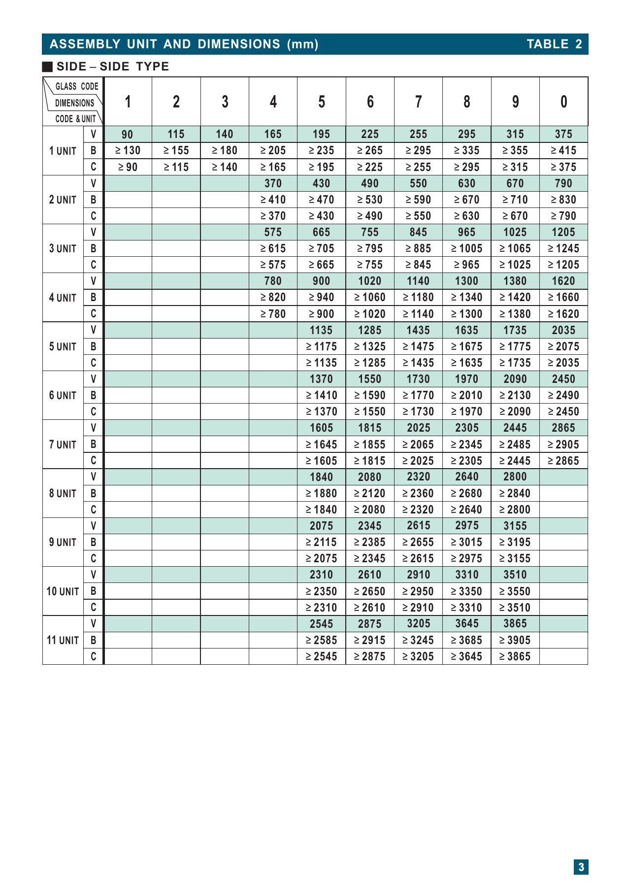
Do not assume interchangeability based on appearance or length. Check the type, chamber and glass, connections, center spacing, visible range and design conditions. The original document uses dimensions including V, B and C; share the existing nameplate and drawing for replacement inquiries.
Related products and specifications
Our technical team can help confirm the options and operating limits for your application.
Discuss your application with Doers ↗Technical specifications
| Parameter | Specification | Unit |
|---|---|---|
| Types | 541: reflex; 542: transparent | |
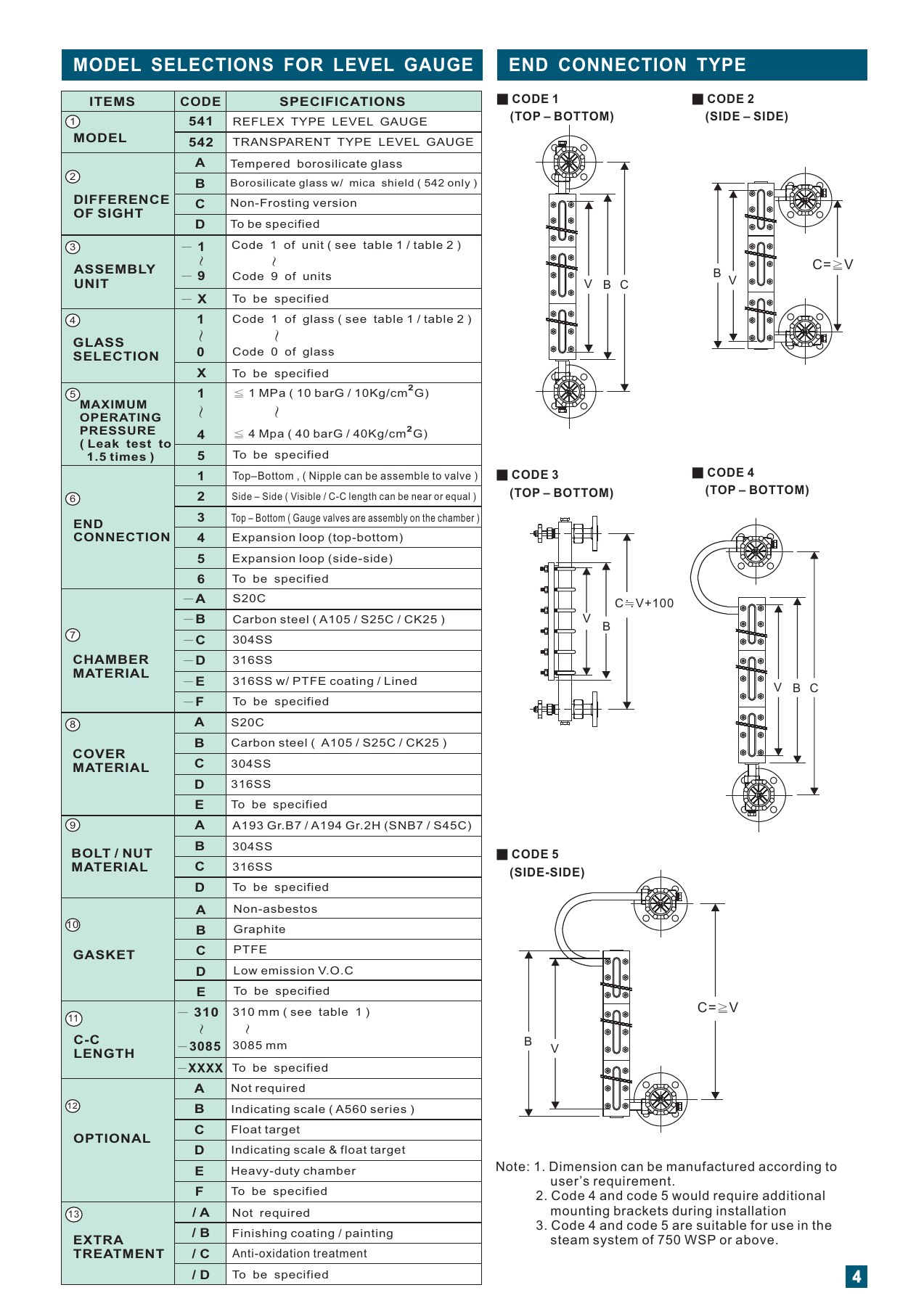
| Chamber materials | S20C, carbon steel, 304/316 stainless steel, or PTFE-coated/lined 316 stainless steel, by configuration | |
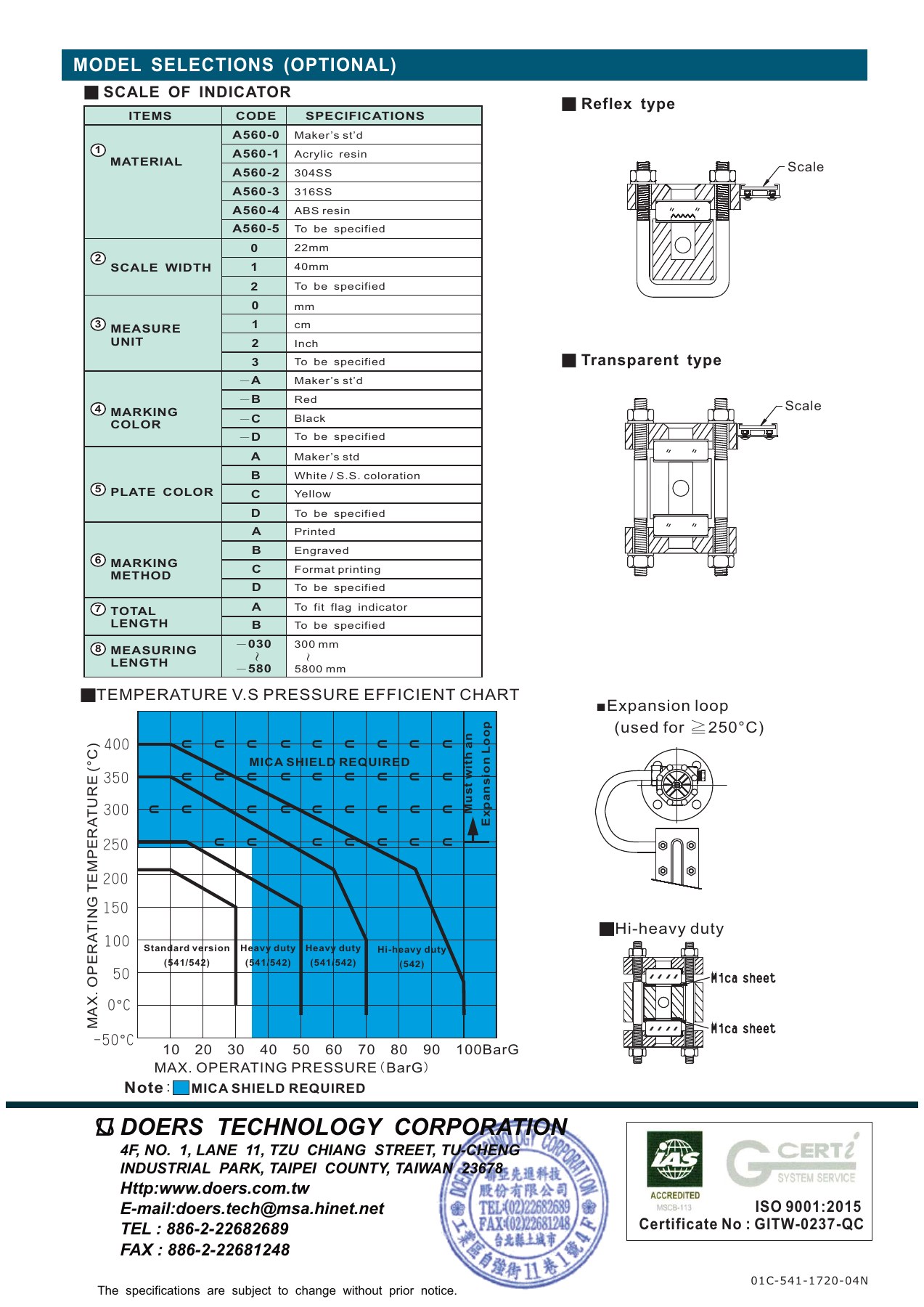
| Glass options | Tempered borosilicate glass; optional mica shields for 542; non-frosting options | |
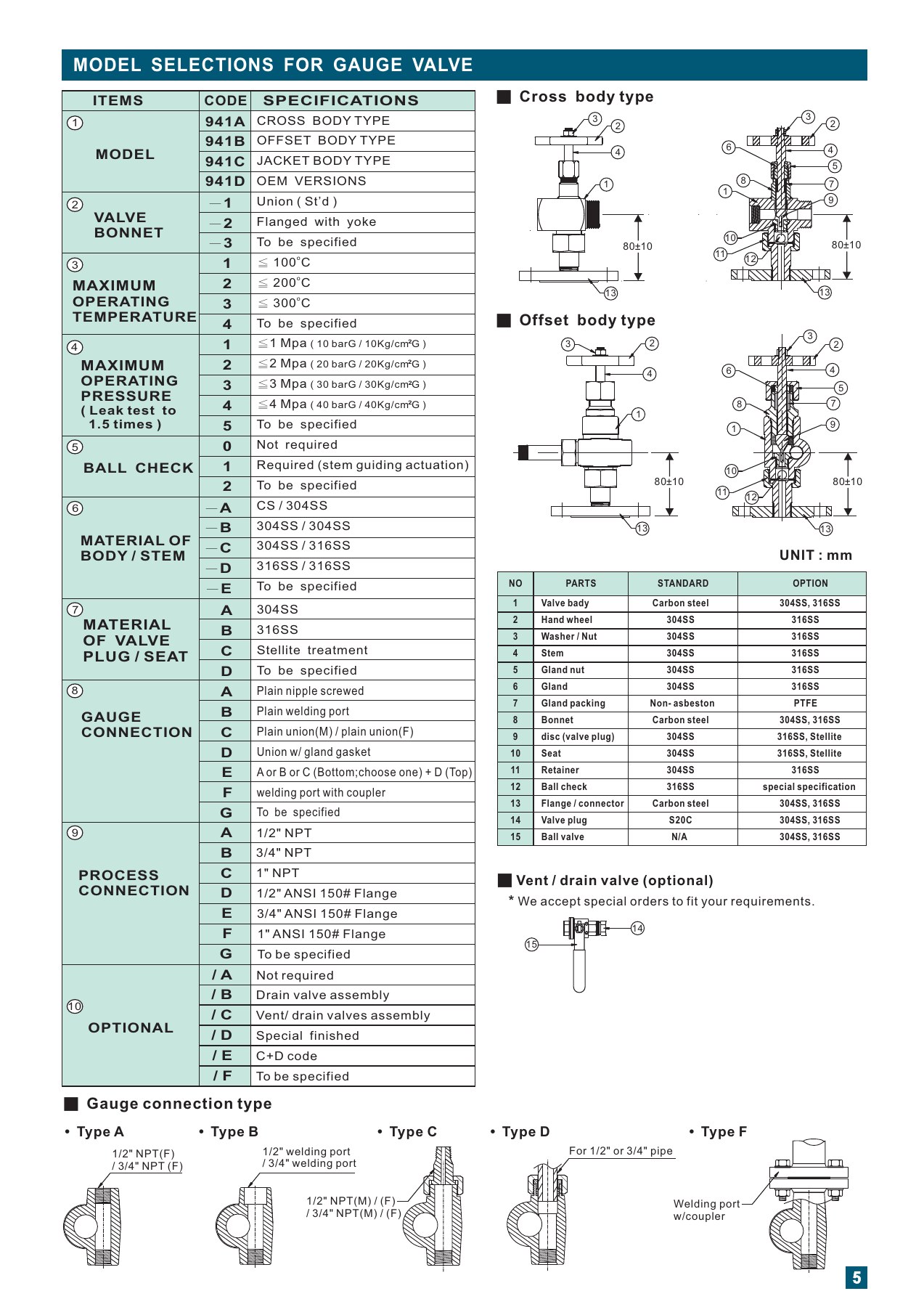
| Connections | Top/bottom, side connections, direct gauge-valve and expansion-loop arrangements | |
| Range and connection spacing | Confirm visible length, number of glass sections and connection centers separately for the mounting arrangement | |
| Operating temperature and pressure | Verify the complete assembly against its temperature-pressure limits; a component rating alone does not establish suitability | |
| Valves and accessories | 941 gauge valves, vent/drain valves, A560 scales and float targets, as specified |
Application and selection notes
- Consider a transparent gauge when fluid color or appearance matters; provide suitable lighting and viewing access.
- Visible length is not the same as connection center-to-center distance. Check the assembly dimensions.
- Check glass, gaskets, valves and chamber together for pressure, temperature and chemical compatibility. Chamber pressure options alone do not establish the assembled gauge rating.
Verify specifications and options against the documents for your model. Select a technical sheet to enlarge it.
Documents
Related products


Explore the principles behind your selection
Need help selecting for your application?
Bring your fluid, temperature, pressure, installation and signal requirements to our technical team.
Level and flow measurement planning →